CYCLOPS Classic
CYCLOPS "Classic" was the first CYCLOPS IFU built as a LIEF-funded upgrade for the Anglo-Australian Telescope's UCLES coude-echelle spectrograph. It is specifically targeted at bright-star spectroscopy (i.e. stars sufficiently bright that observations of them contain negligible sky flux).
It was funded and built as a collaborative effort between UNSW, AAO, U.Sydney, ANU and Monash.
It replaces the 5 mirror Coude train, with a Cassegrain-fed optical-fibre bundle, which reformats a ~3" diameter aperture into a pseudo-slit which is 0.63" wide and 15 elements long (or about ~14" on the sky), allowing it to deliver similar throughput to the old mirror train, but with improved spectral resolution (λ/Δλ=70000 compared to 45000 with a 1" slit) and from an aperture equivalent to a 2.45" diameter, which better matches typical AAT seeing conditions than a 1" slit.
CYCLOPS Classic IN BRIEF
IFU: 15 x 0.6" close-packed hexagons, equivalent to a 2.45" diameter aperture (ie. 4.7 asec2) on sky. (12 working firbres)
PSEDUO-SLIT: 0.63"x14"
λ/Δλ RESN: 70,000
THROUGHPUT: for typical seeing conditions at the AAT (1.5") CYCLOPS collects 70% more photons than the Coude train + 1" slit.
UCLES ECHELLE: 79l/mm
TYPICAL WAVELENGTH COVERAGE WITH EEV:
-
•4550-7350Å (mid)
-
NB: Wavelength coverage is complete for λ<5400A. At λ>5400A there are gaps between orders, which grow with wavelength. For example in the 5000-6000A the 79l/mm echellogram coverage is 30% of that obtained with the 31l/mm.
AVAILIBILITY: CYCLOPS can be applied for in any AAT proposal, though at present proposers are strongly recommended to discuss them in advance with AAO staff or Chris Tinney.
LINKS
-
•CYCLOPS News - with updates from commissioning runs.

Page prepared by Chris Tinney,
CYCLOPS Project Scientist.
Last updated 18 July 2023.
-
CYCLOPS Classic
-
-
The following information on CYCLOPS assumes you are familiar with the basics of echelle spectroscopy using the AAO's UCLES spectrograph. Please consult the UCLES Manual and the UCLES Cookbook, first before trying to use this guide to CYCLOPS observing.
-
-
1.Current Status & Issues
At the time of writing, CYCLOPS has completed four commissioning runs at the AAT (June - Feb 2011), and has been deemed fully commisisoned. The ARC LIEF grant under which it was funded has been finalised.
The current fibre bundle has 20% of its total fibres (ie. 3 out of 15) missing (see above), and the throughput of the fibres installed varies significantly (the worst 3 fibres having about 25% worse throughput than the best. UNSW funds have been identified to manufacture of new bundle with all 15 fibres installed and simultaneous ThAr, which should be available at the end of 2011.
-
2.General Design
-
-
CYCLOPS has a relatively simple optical and mechanical design. It consists of three main components; a
-
•Cassegrain Unit; the
-
•Fibre Bundle; and, a
-
•Pre-slit Unit.
-
The Cassegrain Unit is mounted permanently on one of the Cassegrain rotator's auxiliary ports, where it is fed by a high-reflectivity folding mirror. The optics in the Cassegrain Unit then direct the AAT's beam (via field lenses and a pupil mask) onto the Fibre Bundle.
-
-
At the Cassegrain end, the Fibre Bundle contains a 15-element hexagonal microlens array, which segements the focal plane, and directs a small pupil-image of the telescope onto each of the 15 fibres in the bundle. These fibres then trace a path through the telescope structure, before entering the UCLES pre-slit area, where they are terminated at the Pre-slit Unit. Because the microlens array is permanently bonded to the fibres, this end of the fibre bundle is attached to the Cassegrain Unit using a kinematic mount, so that it can be detached and safely stored on the wall of the Cassegrain cage when CYCLOPS is not in use. Tests show that the kinematic mount repositions the microlens array back to better than 0.03" on the sky (or better than a 20th of the size of a single 0.6" microlens aperture on sky).
-
-
The Pre-slit Unit extracts light from the fibre bundle, and reforms it into 15 apertures laid out in the format of a "pseudo-slit", which is injected at f/36 into UCLES (the usual UCLES slit being suitably opened to allow this to happen). The Pre-slit Unit is also installed on kinematic mounts, so that it can be removed to allow normal UCLES operations. Tests of the re-positioning accuracy of this mount indicate that it repositions arc lines to better than a tenth of an UCLES pixel.
-
-
Note that the pre-slit unit is designed to pack the fibres in the pseudo-slit together as close as is physically possible - CYCLOPS was not designed with spatial reconstruction in mind. As such, the mean centre-to-centre spacing is 5.4 pixels in the spatial direction, and this is just 1.5 times the mean FWHM in the spatial direction (which is 3.5 pixels).
-
-
Calibration is achieved by using pneumatically inserted mirrors to direct light from either a ThAr lamp, or a Quartz lamp, onto the face of the microlens array. Arcs and flats acquired in this way are (or course) fed via the bundle. Observers may also wish to acquire "slit flats" - i.e. flats acquired using UCLES in the same instrument configuration as when used with CYCLOPS, but with the UCLES calibration unit using being used to illuminate the UCLES slit to obtain a 'smooth' flat. This can be done during the day by removing the pre-slit unit and manually moving the UCLES mirror slide into position - AAT staff can assist with obtaining these flats. (See section 6.4 below for more details).
-
-
Guiding is achieved using a dedicated guide camera built into the CYCLOPS Cassegrain Unit. This picks off a 60"x60" field from the AAT beam (using a 1% beamsplitter) before it reaches the microlens array. This field is re-imaged to give a suitable scale of for guiding. In addition the other side of the beam splitter has a retro-reflector installed behind it, so that the guide camera can not only see light picked off by the beam-splitter as it comes from the telescope, but can also pick off light coming from the microlens array (when the fibre bundle is back-illuminated), and send it (via the retro-reflector) onto the guide camera. This back-illumination system is used for aligning the microlens array with the guide camera, and (most importantly) for determining the pixel position on the guide camera that will keep a star aligned on the microlens array.
-
-
-
1.2 On-sky Layouts of the IFU (Integral Field Unit) and Guider
-
-
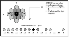
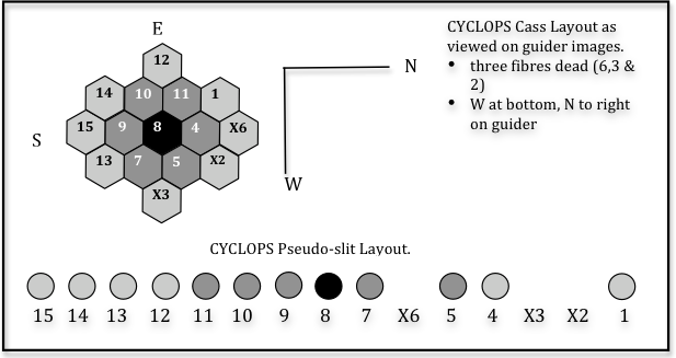
The figure below summarises the physical layout of the CYCLOPS IFU on-sky, as determined on the second CYCLOPS commissioning run in Sep 2010. It is now rotated so that the long-axis of the IFU runs N-S.
-
-
CYCLOPS IFU and Pseudo-slit layout as at Sep 2010.
-
-
-
-
IFU
-
-
•The IFU's long axis runs N-S.
-
•The microlenses are 0.6" in 'diameter' (ie. measured from one flat side to another), giving the full IFU dimensions of 3.0" x 2.76", with a collecting area of 4.7 sq.asec. At present, of course, only 12 of the 15 fibres work (the dead ones are indicated with 'X's in the image above).
-
-
GUIDER
-
•The Guide Camera sees a much larger area than is illuminated by the beam-splitter. To save read times for the guide camera, it should always be operated windowed down to 600x600 window, starting at pixel (500,300).
-
•The Guide Camera display produces an image with W at the bottom and N at the right of the image.
-
•The Guide Camera is used unbinned, and has a scale of 0.274±0.002"/pix.
-
•The CYCLOPS Cassegrain Unit was designed to suffer no appreciable flexure, and as of Feb 2001 it has been demonstrated to do so.
-
-
1.2 Controlling the Pseudo-slit
-
The pseudo-slit formed by the 15 fibres aligned in the Pre-slit unit, is projected into the UCLES spectrograph through the existing UCLES slit. This means you need to set-up the UCLES slit such that it appropriately passes light from CYCLOPS.
-
-
FIBRE PSEUDO-SLIT
-
•The UCLES slit and CYCLOPS pseudo-slit are aligned parallel to each other when the UCLES slit angle is set to SA=-8.4 degrees (note that the UCLES Slit Angle (SA) is the sum of SA+SA offset on the UCLES GUI, which at the moment is -1.0, so a slit angle of -7.4 deg is used in this case.)
-
•An UCLES slit length of 14.5" matches the slit length of the CYCLOPS pseudo-slit.
-
•The UCLES slit and the CYCLOPS pseudo-slit are slightly offset from each other in the slit width direction (ie. perpendicular to the slit length direction when the slit is at SA=-8.4), so you need to open the UCLES slit width up to make sure all the fibre light gets through. It is recommend you observe with the UCLES slit set to SW=4", SL=14.5", SA(total)=-8.4deg
-
•The centre of the UCLES slit 'length' direction is between fibres 7 and 8. You can stop the slit length down to mask out fibres, but you can't stop it down enough to use CYCLOPS with the 31l/mm echelle - you'd need to stop the slit to 7" to get the central 7 fibres, and the longest the 31l/mm echelle slit can be is 5.5".
-
•Different lengths of UCLES slit can be used to allow different sets of fibres to pass light into UCLES. Or more usefully for selecting fibres to back-illuminate as is discussed below.
-
-
VIBRATOR
-
•The CYCLOPS Pre-slit Unit includes a mechanical vibrator that shakes the fibre bundle at ~20Hz. This should be turned on whenever CYCLOPS is being used, in order to minimise the impact of model noise on the fibre throughput.
-
-
1.3 Using the Guider + Retroreflector
-
As noted above the CYCLOPS guider simultaneously views both a 1% pick-off from the AAT focal plane, and a 1% pick off from light coming from the microlens array. The latter will be negligible, except when the fibre bundle is being back illuminated. However, it means that back illumination can be used to locate the (X,Y) position of the microlens array centre on the Guide Camera.
-
-
Before most observing runs, therefore, it should be standard practice to back-illuminate the pre-slit unit (as described below) and measure the position of the microlens array on the guide camera (when used in its standard window) - in Sep 2010 this position was [X,Y]=[298.9, 245.2] - this is the position you should guide at when the telescope is at the zenith.
-
-
-
1.4 Looking at your images
-
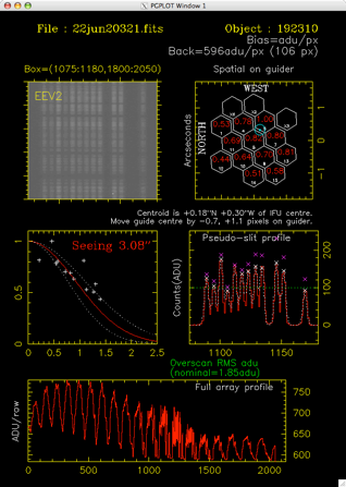
To enable observers to analyse the data they are acquiring, so that they can check whether the star is centered on the IFU, and what the seeing is like, a perl script has been written that will "post-process" a raw image. When observers are logged into the standard UCLES observing account they can use the following command
-
-
~saaps/cyclops_acq filename.fits
-
-
cyclops_acq has the following options
-
-
cyclops_acq [-g] [-d pgplot/dev] filename.fits [x1 x2 y1 y2]
-
-
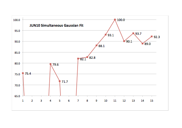
-g - will do a multiple simultaneous Gaussian fit to all the fibres. This works pretty well in most cases, though it will sometimes fail. If it does repeat without the -g option as thesimple 'peak' measurement also works pretty well.
-
-d pgplot/dev - provide a PGPLOT device specification. If unspecified
-
results will display on a /xs window on the current device.
-
x1 x2 y1 y2 - a box to analyse. The default is 1075 1180 1800 2050
-
-
Note that cyclops_acq will not work currently with the detector binned in the X direction. I will try to get this to run, though the lack of spatial information may make that problematic.
-
-
The script collapses the counts in the specified box, to produce a profile of the fibres illuminated. It then identifies peaks, estimates their strength, corrects for the known fibre throughputs, and tries to estimate how far the 'centre of mass' of the light is from the IFU centre. If you use the -g option (which should be the default unless it fails) a simultaneous Gaussian fit will be used to estimate the peak heights. It will also try to do a 'radial fit' to the fluxes it measures in the fibres, to provide a seeing guesstimate.
-
-
The multi-gaussian fit sometimes fails with an uninvertible matrix error. When this happens try changing the box size slightly (ie slightly larger or smaller in Y). If it continually fails, then use the non-gaussian fitting mode (ie without the -g option).
-
-
The code knows about the current orientation of the IFU on the sky, and will provide suggested offsets to apply to the guider X,Y position, that will bring the peak flux from your star to the centre of the IFU.
-
-
-
-
-
3.Throughput
-
2.1 Relative Throughput
-
Observation of the dome screen, when illuminated by every light that can be possibly turned on in the AAT dome, allows us to look at the relative throughputs of the fibres in the current bundle. These have been analysed using the multiple-simultaneous Gaussian fit mode of cyclops_acq to obtain relative counts through each fibre, and then normalised so that the best fibre (fibre 11) has value 100%. The resulting throughputs have a scatter abut their mean values of ±2% for each fibre.
-
-
-
We see that the worst quartile (ie worst three) of the available fibres have 20% lower total throughput than the best quartile. The other 6 fibres lie in between.
-
-
If all 12 fibres had throughput as good as the best current fibre, the total throughput of the bundle would be increased by 16%. If we had all 15 fibres working that well, we would have 45% more throughput than the current bundle.
2.2 Total Throughput
-
Observations of spectro-photometric standards were obtained, however this data has not yet been analysed.
-
What we do know from the comparison of the same objects observed as part of the AAPS (with the 31l/mm echelle and a 1"x3.5" slit in 1.2-1.4” seeing, is that the counts-per-spectral-pixel at the blaze peak near 5360A was approximately the same as that obtained with UCLES+79l/mm+CYCLOPS in 2” (or worse) seeing. -
-
We need data in well characterised CYCLOPS seeing of 1.2-1.4" to make this comparison more robust. However, if would appear that the current sub-optimal bundle has similar throughput (in worse than median seeing), to that obtained with the Coude train (in better than median seeing). Of course, it also delivers higher resolution.
-
4.Resolution
Analysis of ThAr spectra acquired with CYCLOPS indicate that the wavelength format delivered is exactly as one would expect for the UCLES 79l/mm echelle, and that consequently spectral resolution is improved in line with the smaller apertures formed by the fibres at the UCLES slit. For these 2.55pix apertures λ/Δλ resolution will be 70,000 across the whole optical range.
-
5.Echelle Format on Detector. Wavelength Coverage
As noted above, the wavelength format delivered, is exactly as one would expect for the UCLES 79l/mm echelle. However, it is worth making a few notes about what this means for CYCLOPS for those who might not have previous experience with the 79l/mm echellogram.
UCLES is used by most observers with the 31l/mm echelle. This has a smaller free-spectral range than the 79l/mm echelle, must be used with a much smaller slit. As a result the 31l/mm echellogram is much more compact, and the EEV detector provides almost complete wavelength coverage out to ~7000A, with many wavelengths at the edges of orders being "measured" multiple times in different orders. Indeed the FSR is small enough that it is only necessary to record ~2750 of the EEV detector's 4096 pixels (by which point the flux in most orders has dropped to less than a half of the peak for that order).
The 79l/mm echellogram is much more spread out - this is good because it allows CYCLOPS to reformat the telescope's focal plane into a long pseudo-slit, but this also means that the wavelength at which gaps in coverage begin to appear between orders is much bluer (at ~5300A). It also means that a much larger CCD window must be read out to reach the edges of each order at which counts have dropped to 50% of that seen at the order's peak (in practice this is the whole EEV CCD) so read-out times will be a little longer.
As an example, I have compared the integrated wavelength coverage afforded by the 31l/mm echelle grating typically used for planet search work in the wavelength range 5000-6000A by the AAPS. Over this wavelength range, the 31l/mm echelle delivers complete wavelength coverage, with many wavelengths being recorded in multiple orders. The actual wavelength gaps we have when using CYCLOPS with the 79l/mm echelle in this rage are quite small - less than 5% of the total wavelength range. However, when one considers the "multiple measures" of many wavelengths delivered by the 31l/mm echelle, then the "integrated" wavelength coverage with the 79l/mm is around 70% of that obtained with the 31l/mm echelle. (Though for this simple calculation I have assumed normalised all order peaks in both echellograms to 1.0 - I am not a million percent sure this is correct, as it would seem to allow the 31l/mm echelle to record >100% of photons at some wavelengths, which I worry is not physically meaningful. Tests will be done directly comparing the 31l/mm and 79l/mm echelles on the next AAPS run).
In any case, here are some example wavelength formats delivered by the 79l/mm echelle with CYCLOPS.
A 'mid' wavelength setting with ET=0.3002 -0.3 EG=-1.050+0.037
(which puts 5000-6000A in the centre of the EEV detector.)
Order Coverage Dispersion
(A) (A/pix)
-
49 4542 4652 0.027
-
48 4635 4749 0.028
-
47 4735 4850 0.028
-
46 4838 4955 0.029
-
45 4945 5065 0.029
-
44 5057 5180 0.030
-
43 5174 5300 0.031
-
42 5297 5426 0.031
-
41 5426 5558 0.032
-
40 5562 5697 0.033
-
39 5704 5842 0.034
-
38 5854 5996 0.035
-
37 6012 6157 0.036
-
36 6178 6328 0.037
-
35 6354 6508 0.038
-
34 6541 6699 0.039
-
33 6739 6902 0.040
-
32 6949 7117 0.041
-
31 7172 7346 0.042
-
6.Observing with CYCLOPS
6.1 Controlling CYCLOPS
-
-
CYCLOPS is controlled by two interfaces - a complex one, and a very simple one.
-
-
1 - The UCLES/CYCLOPS ODC - The first (complex) interface is a version of the UCLES ODC interface that is exactly the same as that usually used to control UCLES, except that control of both the Beam Rotator and the Mirror Carriage are deactivated (since those parts would foul the CYCLOPS Pre-slit Unit if they were moved and neither are used when observing with CYCLOPS).
-
-
You will run most of your observing from this interface - for detailed information on how to control UCLES via this interface see the UCLES/ODC Interface page.
-
-
Insert image of CYCLOPS/UCLES ODC here.
-
-
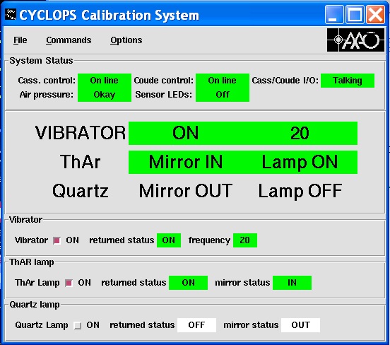
2 - The CYCLOPS Calibration Unit GUI - The second interface is a simple GUI that controls the additional calibration functions that CYCLOPS has in its Cassegrain unit, and which also turns the fibre Vibrator on and off.
-
-
-
-
Acquiring calibration exposures is as simple as turning on the right lamp, making sure you have the exposure time and object name and exposure type correct in the UCLES/CYCLOPS ODC gui, and hitting the 'ARC' or 'FLAT' buttons to start an exposure.
-
-
Acquiring a science exposure is as simple as turning the lamps off. The lamps have a hardware time-out function that will turn them off after a few hours, so they don't get worn out if you forget. But the system won't turn the lamps off simply because you have hit the 'Run' button in UCLES instead of the 'Arc' or 'Flat' buttong. Turing the lamps on and off is your job.
-
6.2 Starting the Software
-
NB: These instructions were current for the Feb 2011 commissioning run. They may change in future, in which case updated instructions will be provided on the whiteboard in the AAT control room.
-
To run the CYCLOPS software you should -
-
(1) login into the usual computer used for UCLES observing, then type (as at Jan 2011)
% drama -v ucles_cyclops_latest -
-
(2) Start the UCLES/CYCLOPS ODC interface by typing
% cyclops1 cyclops_em cyclops_guider (for CCD1)
or
% cyclops2 cyclops_em cyclops_guider (for CCD2).
The CCD you are running will be on the small whiteboard in the control room. You can leave out the cyclops_em if not using the exposure meter, or the cyclops_guider if not using the guider. -
(3) Once that system has started up, open the the CYCLOPS calibration gui by typing
% newcyclopsgui -
-
You should now be ready to start taking data!
-
-
(4) If you will be using the SuperAAPS observing system to take data then start that as well
% cd saaps
% saaps & (NB: saaps5 command not needed, as it is now the default). -
-
-
Shut down / Restart - If the CYCLOPS system is running and you need to shut it down, then follow the usual process for UCLES observing.
-
•First, try to shut things down from the CCD Loader window using the "Commands->Exit" menu item. If you do this during your run, make sure to NOT park the echelles!
-
•If that doesn't work then type 'cleanup' in the window that you started the gui interfaces from.
-
•If after doing that you still can't restart the interfaces, then do the cleanup again, and then reset aatvme15, wait a few minutes, then restart the software. (If you don't know how to reset aatvme15, then call for the afternoon technician or night assistant at this point).
6.3 In the Afternoon Before Observing
-
-
Turn on the fibre vibrator. Fibre vibration is controlled from the calibration GUI. The vibration should be turned on and left one for the rest of your run.
-
-
Back-illuminate the fibre bundle and check the guide point. This requires entering the UCLES spectrograph, and should only be done in consultation with your afternoon technician. It should not need to be done more than once a run.
-
-
(a) Mount one of the AAT's small LED torches on a retort stand directly in front of the UCLES prisms, such that the torch shines back at the collimator. This will direct a vaguely f/36 beam back through the UCLES shutter (which needs to be open for this to work - the easiest way to do that is start a 3 hour dummy exposure) and into the Pre-slit Unit's fibre pseudo-slit. If you put your head in front of the shutter and look back at the collimator, you should see the torch shining brightly at you.
-
-
(b) Next you need to adjust the UCLES slit, such that only the central fibre of the pseudo-slit is illuminated - set the slit to be 4.0" wide by 2.0" long and set SA=+10°.
-
-
(Some more information on this - with the slit angle in its "default" orientation for CYCLOPS of -8.4°, the UCLES slit has the centre of its motion in the "length" direction between fibres 7 and 8 on CYCLOPS. Unfortunately, you cannot make the slit short enough to illuminate only the central fibre (fibre 8). However, you can adjust the fibres that get illuminated by changing the slit length. And if you twist the slit angle, and make the slit short and narrow you can get just fibre 8 illuminated. Here is a guide to what you can do -
-
•a 2.0” long slit at SA=-8.4° illuminates fibres 9,8,7;
-
•a 4.0” long slit at SA=-8.4° illuminates fibres 10,9,8,7,6(dead);
-
•a 6.0” long slit at SA=-8.4° illuminates fibres 11,10,9,8,7,6(dead),5;
-
•a 10.0” long slit at SA=-8.4° illuminates 13,12,11,10,9,8,7,6(dead),5,4,3(dead); and,
-
•a 2.0" long slit at SA=+10.0° illuminates fibre 8 alone.)
-
-
(c) You can now use the guide camera (with very short exposures of ~0.1s) to take images of the microlens array through the retroreflector - you will see a point source that corresponds to fibre 8. Use the "Pick Object" function in the Guide Camera skycat display to record the centroid of this point source. This is where the centre of the microlens array should map to on your guide camera - however as noted above in section 1.3, it seems a fixed offset needs to be applied to this measured back-illumination position to get your guide pixel position. See section 1.3 for details.
-
-
(d) Once you have done that, you can remove the torch doing the back illumination, stop the dummy exposure holding the shutter open, and put the UCLES slit backinto the configuration you will use for observing with CYCLOPS.
-
-
Open the UCLES slit so that light from the CYCLOPS fibre bundle can shine through -
it is recommend you observe with the UCLES slit set to SW=4", SL=14.5", SA(total)= -8.4deg. -
-
Position echelle's for the desired wavelength configuration - do this in the normal way for UCLES. You will get an approximate wavelength configuration that is pretty good using the usual UCLES commands to move the 79l/mm echelle to a stated central wavelength. Fiddling with the angles of the echelle grating (ie. Echelle Theta [ET] and Echelle Gamma [EG]) should only be necessary if you really have a definite line that you absolutely must have that is near the edge of the detector.
-
-
An example of the wavelength coverage obtained with one ET,EG combination is provided above in section 4, and will be updated with further configurations used for CYCLOPS as experience is developed and data is reduced.
-
-
Rotate the detector (if required) - you may wish to rotate the detector such that the echelle orders in a wavelength range of particular interest, are vertical on the detector. The standard UCLES set-up procedures for this should be adequate, though you will need a technician to actually rotate the detector, once you have worked out the correction to be applied. However, you cannot adjust the slit angle - this is fixed by the fixed position of the pseudo-slit.
-
-
Focus spectrograph - the standard UCLES setup-scripts for focussing the spectrograph (ie. adjusting the collimator focus (CF) for best image quality) using the Hartman masks should work. Alternatively, a simple script to analyse a focus sequence for sharpest images is being developed for CYCLOPS.
-
-
Acquire slit flats - once you have determined your instrumental configuration for the coming night, you can acquire a set of slit flats (or even better wait until the end of the night so you know exactly what your setup was). This is fiddly and involves handling the pre-slit unit, so you need to get help from your afternoon technician and/or night assistant.
-
-
A - the technician will very, very carefully remove the Pre-slit Unit from its kinematic mounts, and manually drive in the mirror slide. This will allow the UCLES calibration unit to illuminate your slit.
-
B - acquire a slit flat using the UCLES flat field lamps and a long slit, without moving the UCLES echelles. This can now be done with the most recent version of the CYCLOPS ODC system, which allows you to turn flat field lamps on and off while the mirror slide is in manual mode. It can also be done with the saaps observing software (which can control the flat field lamp on UCLES as well as running CYCLOPS)
You may wish to narrow the slit down from the "default" 4 arcsecond width for use with CYCLOPS to something more like 1-2 arcseconds. -
C - Turn the UCLES flat field lamps back off, and have the technician manually drive the mirror back out of the way, and very,very,very carefully put the Pre-slit unit back.
6.4 Observing & Calibration
-
Acquisition - as CYCLOPS is designed for observing bright objects, your science target will usually be the only bright object visible within the guide camera's ~1 arcmin field of view. Acquisition simply involves moving that object to the guide pixel location. In most cases this can be achieved by simply starting the guiding, which will quickly drag the object to the guide position.
-
-
If your field contains multiple objects, you will need to use a finding chart to advise the night assistant as to how to bring your preferred target onto the guide pixel.
-
-
Observing - Observing your target is then simply a matter of acquiring any calibrations you need (most likely a ThAr arc before a science exposure) as described above, and then starting science exposures. You may also wish to acquire an arc at the end of the science exposures as well, and potentially a flat (which will be useful for tracing out the fibres if your target is faint).
-
-
After each science exposure it is worth running the ~/saaps/cyclops_acq script (see above) to check that you are getting the counts you wanted, and that the object is staying centred on the microlens array.
-
7.Reducing CYCLOPS Data
Exactly what is the best means for reducing CYCLOPS data is being learnt as you read this. In principle, the CYCLOPS spectra can just be treated as being identical to UCLES 79l/mm slit spectra - for most general purpose echelle spectroscopy this should be more than adequate. The major "wrinkles" to this general procedure are likely to be
-
•flat fielding (with a slit flat)
-
•correction for the significant slit rotation across the field, and
-
•fibre offsets perpendicular to the slit.
Flat fielding. As noted above, getting a smooth pixel-to-pixel correction for the CCD out of CYCLOPS fibre flats is likely to be difficult. As such, acquiring day-time "slit flats" using your night-time instrumental configuration is important. These flats (suitably processed) should be able to be used to correct the pixel-to-pixel response of the detector to high precision. A combination of fibre-flats and night-time standards should then enable you to both trace your spectra and derive corrections for the spectrograph response function vs wavelength. Acquiring slit flats with slits of various lengths will enable you to model and remove the scattered light background from your slit flats.
Rectifying the echellogram. Because CYCLOPS uses the maximum "slit length" made available by the 79l/mm echelle grating, the apparent "rotation" of the slit over the field of view is substantial. If you simply collapsed your spectra without correcting for it, you would substantially degrade the resolution of your spectra (to the point you'd be getting no advantage from using CYCLOPS!). "Rectifying" the CYCLOPS image to make all the 'pseudo-slits' formed by arc-lines horizontal across the field will therefore be required. (Alternatively, you can develop a model for the rotation over the field and have this drive an optical extraction - this is the technique being developed by the AAPS team).
Take care with fibre offsets. Finally, (as noted above) the fibres that form the pseudo-slits are aligned into a slit to high tolerances, but are not perfect - their peak to peak variation is around 4% of the width of a single fibre. For most observers this will be irrelevant. For those interested in science goals at a very small fraction of a spectral FWHM (e.g. precision Doppler velocities) care will have to be taken in the analysis to account for the varying amounts of light that will come through each fibre as seeing and tracking vary their relative illuminations.

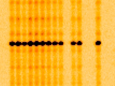
The image above shows a section of a ThAr arc spectrum obtained with CYCLOPS - each element of the IFU is recorded by UCLES as a single spectrum with spectral FWHM=2.55 pixels. In this image, three fibres are missing (fibres 2,3 and 6) producing a distinctive pattern on the spectrograph.