CYCLOPS2
CYCLOPS2 started life as a new-and-improved fibre bundle for CYCLOPS Classic, and was supplemented by new harware to mount this bundle on the AAT in the form of the AAO's CURE Cassegrain focus upgrade. CYCLOPS2 has 17 working fibres - 16 that see the sky and a 17th for doing simultaneous wavelength calibration.
It replaces the 5 mirror Coude train, with a Cassegrain-fed optical-fibre bundle, which reformats a ~3" diameter aperture into a pseudo-slit which is 0.63" wide and 15 elements long (or about ~14" on the sky), allowing it to deliver similar throughput to the old mirror train, but with improved spectral resolution (λ/Δλ=70000 compared to 45000 with a 1" slit) and from an aperture equivalent to a 2.45" diameter, which better matches typical AAT seeing conditions than a 1" slit.
CYCLOPS2 IN BRIEF
IFU: 16 x 0.6" close-packed hexagons, equivalent to a 2.45" diameter aperture (ie. 5.0 asec2) on sky.
PSEDUO-SLIT: 0.63"x14.5"
λ/Δλ RESN: 70,000
THROUGHPUT: for typical seeing conditions at the AAT (1.5") CYCLOPS2 collects 80% more photons than the Coude train + 1" slit.
UCLES ECHELLE: 79l/mm
TYPICAL WAVELENGTH COVERAGE WITH EEV:
-
•4550-7350Å (mid)
-
NB: Wavelength coverage is complete for λ<5400A. At λ>5400A there are gaps between orders, which grow with wavelength. For example in the 5000-6000A the 79l/mm echellogram coverage is 30% of that obtained with the 31l/mm.
AVAILIBILITY: CYCLOPS2 can be applied for in any AAT proposal, though at present proposers are strongly recommended to discuss them in advance with AAO staff or Chris Tinney.
LINKS
-
•CYCLOPS News - with updates from commissioning runs.

Page prepared by Chris Tinney,
CYCLOPS Project Scientist.
Last updated 18 July 2023.
-
-
CYCLOPS2
-
-
-
-
-
-
-
-
The following information on CYCLOPS2 assumes you are familiar with the basics of echelle spectroscopy using the AAO's UCLES spectrograph. Please consult the UCLES Manual and the UCLES Cookbook, first before trying to use this guide to CYCLOPS observing.
-
-
1.Current Status & Issues
CYCLOPS2 is now fully commissioned and available for all observers to propose to use. All 16 fibres that see the sky work, and the simultaneous ThXe fibre works quite well. Throughput of CYCLOPS2 is (on average) 10% better than for CYCLOPS Classic. The post-processing script for CYCLOPS2 works reasonably well and can be used with the detector either unbinned, or binned by 2 in X.
A dual vibrator system is used for mode scrambling at both freuencies of a few Hertz and 20-20 Hertz.
Spectral image quality is the same as for CYCLOPS Classic. The fibres are ~10% more closely packed on the detector.
-
2.Starting the CYCLOPS2 software
-
•Login into the usual computer used for UCLES observing, and then type:
%drama -v cure6
-
•Start the UCLES/CYCLOPS2 ODC interface by typing:
% cyclops22 cyclops_guider cyclops_em -
•If you want to see what the telescope does, create a mirror of the tcs.
% tel & -
•Once that system has started up, open the the CYCLOPS2 calibration gui by typing
% curegui &
You will get a gui that looks like this: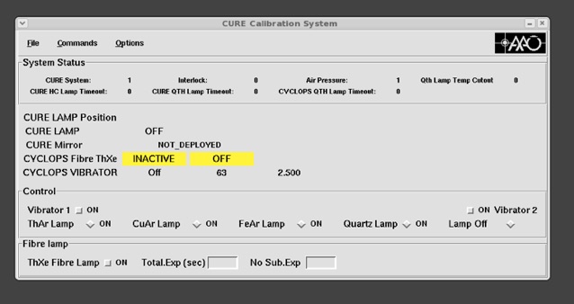
Using this GUI, turn the vibrator on and leave it on for the rest of the night. It should be turned off at the end of the night. The numbers (63 and 2.5) indicate that the two vibrators are working. They will go to zero if the vibrators stop. You can ask the night assistant to check if the vibrators are going. -
•If observing for HAT South or AAPS programs, then start the SAAPS software:
% cd saaps (Actual directory is /instsoft/instusers/aatinst/saaps/)
% saaps &
saaps brings up a gui that looks like the folloowing. For ducumentation on saaps see the SuperAAPS pages.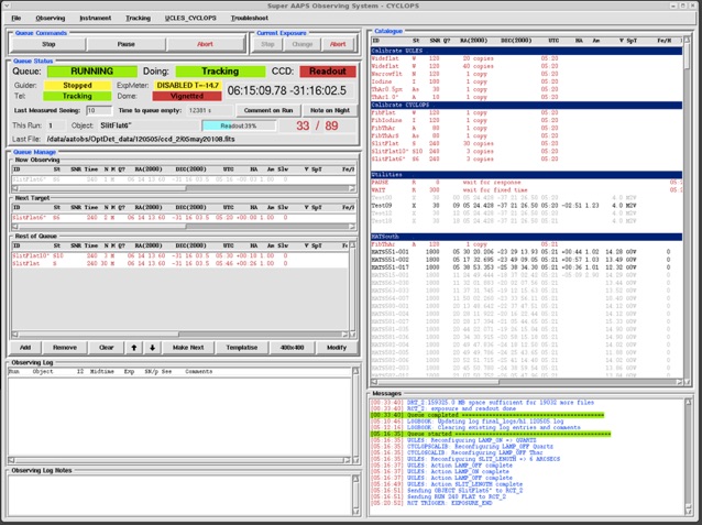
-
3.Looking at your data
-
-
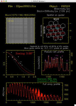
To enable observers to analyse the data they are acquiring, so that they can check whether the star is centered on the IFU, and what the seeing is like, a perl script has been written that will "post-process" a raw image. When observers are logged into the standard UCLES observing account they can use the following command
-
-
~saaps/cyclops_acq filename.fits
-
-
cyclops_acq has the following options
-
-
cyclops_acq [-g] [-C1] [-C2] [-d] filename.fits [x1 x2 y1 y2]
-
-
-C1 force process as a Cyclops Classic image (the default is to work this out from the file).
-
-C2 force process as a CYCLOPS2 image (the default is to work this out from the file).
-
-sim force process as having a simultaneous ThXe (default is to look in file header to determine this)
-
-g - will do a multiple simultaneous Gaussian fit to all the fibres. This works pretty well in most cases, though it will sometimes fail. If it does repeat without the -g option as thesimple 'peak' measurement also works pretty well.
-
-d - display results in a PGPLOT pop-up window.
-
x1 x2 y1 y2 - a box to analyse. The default is 1075 1180 1800 2050
-
-
There are also other options. Use cyclops_acq with no options to display them.
-
-
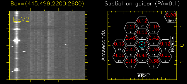
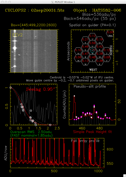
The script collapses the counts in the specified box, to produce a profile of the fibres illuminated. It then identifies peaks, estimates their strength, corrects for the known fibre throughputs, and tries to estimate how far the 'centre of mass' of the light is from the IFU centre. If you use the -g option (which should be the default unless it fails) a simultaneous Gaussian fit will be used to estimate the peak heights. It will also try to do a 'radial fit' to the fluxes it measures in the fibres, to provide a seeing guesstimate.
-
-
The multi-gaussian fit sometimes fails with an uninvertible matrix error. When this happens try changing the box size slightly (ie slightly larger or smaller in Y). If it continually fails, then use the non-gaussian fitting mode (ie without the -g option).
-
-
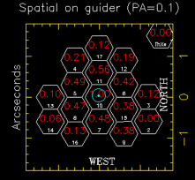
The code knows about the current orientation of the IFU on the sky, and will provide suggested offsets to apply to the guider X,Y position in unbinned pixels, that will bring the peak flux from your star to the centre of the IFU. Note that the guider is almost always used with binned x2 pixels, so you'll need to divide these offsets by 2 before asking the night assistant to apply them to the guiding mark.
-
-
4.Setting Up
-
Position echelle's for the desired wavelength configuration - do this in the normal way for UCLES. You will get an approximate wavelength configuration that is pretty good using the usual UCLES commands to move the 79l/mm echelle to a stated central wavelength. Fiddling with the angles of the echelle grating (ie. Echelle Theta [ET] and Echelle Gamma [EG]) should only be necessary if you really have a definite line that you absolutely must have that is near the edge of the detector.
-
-
Rotate the detector (if required) - you may wish to rotate the detector such that the echelle orders in a wavelength range of particular interest, are vertical on the detector. The standard UCLES set-up procedures for this should be adequate, though you will need a technician to actually rotate the detector, once you have worked out the correction to be applied. However, you cannot adjust the slit angle - this is fixed by the fixed position of the pseudo-slit.
-
-
Focus spectrograph - the standard UCLES setup-scripts for focussing the spectrograph (ie. adjusting the collimator focus (CF) for best image quality) using the Hartman masks should work. Alternatively, you can simply take a sequence of observations over the range of colimator fpcus travel (CF=-10 to +5) and see where the images are best. Using the Simultaneous ThXe works well for this because you get just ONE set of images.
-
-
Acquire slit flats - once you have determined your instrumental configuration for the coming night, you can acquire a set of slit flats (or even better wait until the end of the night so you know exactly what your setup was). This is fiddly and involves handling the pre-slit unit, so you need to get help from your afternoon technician and/or night assistant.
-
-
A - the technician will very, very carefully remove the Pre-slit Unit from its kinematic mounts, and manually drive in the mirror slide. This will allow the UCLES calibration unit to illuminate your slit.
-
B - acquire a slit flat using the UCLES flat field lamps and a long slit, without moving the UCLES echelles. This can now be done with the most recent version of the CYCLOPS ODC system, which allows you to turn flat field lamps on and off while the mirror slide is in manual mode. It can also be done with the saaps observing software (which can control the flat field lamp on UCLES as well as running CYCLOPS)
You may wish to narrow the slit down from the "default" 4 arcsecond width for use with CYCLOPS to something more like 1-2 arcseconds. -
C - Turn the UCLES flat field lamps back off, and have the technician manually drive the mirror back out of the way, and very,very,very carefully put the Pre-slit unit back.
-
5.On Sky - Checking Fibre Centring and Focus.
In twilight we now do centring the star on the fibre bundle and focusing:
-
6. Go to a very bright star - you can start this at about 20 minutes before 12 degree twilight.
-
7. Set up doing short exposures in 1x1 binning - in saaps you can do this by taking short observations converted to "400x400" mode.
-
8. Once at the star make sure you are guiding.
-
9. Adjust the centering
-
•Take an image (if using saaps pause the queue during the exposure, then ‘continue’ when you are ready to take another)
-
• Look at the post-processing. Is the object centred? Make sure to look at the plots, not just the suggested move. Make sure the suggestion makes sense. With only 16 fibres this is not 100% reliable. Brain power is required!
-
• The script will suggest a move of the X,Y guiding position in *unbinned* pixels. Divide these by two (to get the binned pixels used on the guider) and ask the NA to move the guide pixel by that amount. NB: They have to stop guding, enter new number in a box, AND HIT ENTER, then restart guiding.
-
• Once its settled, take another exposure and repeat to iterate towards a guide centre you believe in. Note that this can be hard in bad seeing. On the other hand in bad seeing its also not critical!
-
10.Now check the telescope focus
-
• Ask telescope operator to move focus down by about 0.6. Unpause, take exposure, re-pause. Analyse image in post process window, move to a new focus up by 0.1, repeat until you travel through a bext focus you beleive in.
-
• Focus records for past runs
-
★CYCLOPS1 May 2012: Focus= 25.6. X, Y pixel on guider was 153.6 and 161.7 respectively (using the guiding windowing we have set up for this program, which is 300x300pixel window).
-
★CYCLOPS1? June 2012 : Focus=25.7, 153.6 and 162.7
-
★CYCLOPS1? August 2012 : Focus=25.6 X,Y=153.95 164.0
-
★CYCLOPS2 April 2013 (measured in 0.6-0.8” seeing so very reliable). FOC=50.15, X,Y=160.0,138.2. Dome temp 12.4C.
-
5.Resolution
Analysis of ThAr spectra acquired with CYCLOPS Classic and CYCLOPS2 indicate that the wavelength format delivered is exactly as one would expect for the UCLES 79l/mm echelle, and that consequently spectral resolution is improved in line with the smaller apertures formed by the fibres at the UCLES slit. For these 2.55pix apertures λ/Δλ resolution will be 70,000 across the whole optical range.
-
6.Echelle Format on Detector. Wavelength Coverage
As noted above, the wavelength format delivered, is exactly as one would expect for the UCLES 79l/mm echelle for both CYCLOPS 2 and CYCLOPS Classic. However, it is worth making a few notes about what this means for CYCLOPS observations for those who might not have previous experience with the 79l/mm echellogram.
UCLES is used by most observers with the 31l/mm echelle. This has a smaller free-spectral range than the 79l/mm echelle, must be used with a much smaller slit. As a result the 31l/mm echellogram is much more compact, and the EEV detector provides almost complete wavelength coverage out to ~7000A, with many wavelengths at the edges of orders being "measured" multiple times in different orders. Indeed the FSR is small enough that it is only necessary to record ~2750 of the EEV detector's 4096 pixels (by which point the flux in most orders has dropped to less than a half of the peak for that order).
The 79l/mm echellogram is much more spread out - this is good because it allows CYCLOPS to reformat the telescope's focal plane into a long pseudo-slit, but this also means that the wavelength at which gaps in coverage begin to appear between orders is much bluer (at ~5300A). It also means that a much larger CCD window must be read out to reach the edges of each order at which counts have dropped to 50% of that seen at the order's peak (in practice this is the whole EEV CCD) so read-out times will be a little longer.
As an example, I have compared the integrated wavelength coverage afforded by the 31l/mm echelle grating typically used for planet search work in the wavelength range 5000-6000A by the AAPS. Over this wavelength range, the 31l/mm echelle delivers complete wavelength coverage, with many wavelengths being recorded in multiple orders. The actual wavelength gaps we have when using CYCLOPS with the 79l/mm echelle in this rage are quite small - less than 5% of the total wavelength range. However, when one considers the "multiple measures" of many wavelengths delivered by the 31l/mm echelle, then the "integrated" wavelength coverage with the 79l/mm is around 70% of that obtained with the 31l/mm echelle. (Though for this simple calculation I have assumed normalised all order peaks in both echellograms to 1.0 - I am not a million percent sure this is correct, as it would seem to allow the 31l/mm echelle to record >100% of photons at some wavelengths, which I worry is not physically meaningful. Tests will be done directly comparing the 31l/mm and 79l/mm echelles on the next AAPS run).
In any case, here are some example wavelength formats delivered by the 79l/mm echelle with CYCLOPS. CYCLOPS2 will do the same.
A 'mid' wavelength setting with ET=0.3002 -0.3 EG=-1.050+0.037
(which puts 5000-6000A in the centre of the EEV detector.)
Order Coverage Dispersion
(A) (A/pix)
-
49 4542 4652 0.027
-
48 4635 4749 0.028
-
47 4735 4850 0.028
-
46 4838 4955 0.029
-
45 4945 5065 0.029
-
44 5057 5180 0.030
-
43 5174 5300 0.031
-
42 5297 5426 0.031
-
41 5426 5558 0.032
-
40 5562 5697 0.033
-
39 5704 5842 0.034
-
38 5854 5996 0.035
-
37 6012 6157 0.036
-
36 6178 6328 0.037
-
35 6354 6508 0.038
-
34 6541 6699 0.039
-
33 6739 6902 0.040
-
32 6949 7117 0.041
-
31 7172 7346 0.042
-
-
7.Back Illumination of the Fibres
This should not in general need to be done anymore - fibre centering using a bright star at the start of the run/night works well.
Back illuminate Fibre - see cgt’s notes (8.Perform Back-illumination Check of the GUIDER x,y position) on website for more info
This is to check the central position on the guider camera where we will need to put the star to ensure the light is going down the fibre.
This requires entering the UCLES spectrograph, and should be done in consultation with your afternoon technician.
(a) Mount one of the AAT's small LED torches on a retort stand directly in front of the UCLES prisms, such that the torch shines back at the collimator. (You should find a retort stand in the UCLES room suitable for doing this). This will direct a vaguely f/36 beam back through the UCLES shutter (which needs to be open for this to work - the easiest way to do that is start a 3 hour dummy exposure) and into the Pre-slit Unit's fibre pseudo-slit. If you put your head in front of the shutter and look back at the collimator, you should see the torch shining brightly at you.
(b) Next you need to adjust the UCLES slit, such that only the central fibre of the pseudo-slit is illuminated - set the slit to be 4.0" wide by 2.0" long and set SA=+10°. SA may take a long time to reach target angle
(Some more information on this - with the slit angle in its "default" orientation for CYCLOPS of -8.4°, the UCLES slit has the centre of its motion in the "length" direction between fibres 7 and 8 on CYCLOPS. Unfortunately, you cannot make the slit short enough to illuminate only the central fibre (fibre 8). However, you can adjust the fibres that get illuminated by changing the slit length. And if you twist the slit angle, and make the slit short and narrow you can get just fibre 8 illuminated.
(c) You can now use the guide camera (with very short exposures of ~0.1s) to take images of the microlens array through the retroreflector - you will see a point source that corresponds to fibre 8. Use the "Pick Object" function in the Guide Camera skycat display to record the centroid of this point source. This is where the centre of the microlens array should map to on your guide camera.
●Open the UCLES slit back up to SW=4", SL=14.5", SA(total)= -8.4deg (set one at a time). Abort the dummy exposure you started to keep the shutter open.
●Dummy exposure: OTC choose Dummy, change bin, set to 30min exposure.
Set up the torch in the coude room to back illuminate the fibre.
The guider window should have a window that is 2x2 binning, 300x300 pixels origin at (?,?). This window is loaded by “set window” and loading up “cyclops beamsplitter only” config file.
In April 2013 the guider center is at 160.0, 138.2
-
8.Reducing CYCLOPS Data
CYCLOPS data reduction is somewhat complicated. In principle, the CYCLOPS spectra can just be treated as being identical to UCLES 79l/mm slit spectra - for most general purpose echelle spectroscopy this should be more than adequate. The major "wrinkles" to this general procedure are likely to be
-
•flat fielding (with a slit flat)
-
•correction for the significant slit rotation across the field, and
-
•fibre offsets perpendicular to the slit.
Flat fielding. As noted above, getting a smooth pixel-to-pixel correction for the CCD out of CYCLOPS fibre flats is essentially impossible. As such, acquiring day-time "slit flats" using your night-time instrumental configuration is important. These flats (suitably processed) can be used to correct the pixel-to-pixel response of the detector to high precision. A combination of fibre-flats and night-time standards should then enable you to both trace your spectra and derive corrections for the spectrograph response function vs wavelength. Acquiring slit flats with slits of various lengths will enable you to model and remove the scattered light background from your slit flats.
Rectifying the echellogram. Because CYCLOPS uses the maximum "slit length" made available by the 79l/mm echelle grating, the apparent "rotation" of the slit over the field of view is substantial. If you simply collapsed your spectra without correcting for it, you would substantially degrade the resolution of your spectra (to the point you'd be getting no advantage from using CYCLOPS!). "Rectifying" the CYCLOPS image to make all the 'pseudo-slits' formed by arc-lines horizontal across the field will therefore be required. (Alternatively, you can develop a model for the rotation over the field and have this drive an optical extraction - this is the technique used for extraction by the HAT South team. Contact Duncan Wright at UNSW for details).
Take care with fibre offsets. Finally, (as noted above) the fibres that form the pseudo-slits are aligned into a slit to high tolerances, but are not perfect - their peak to peak variation is <4% of the width of a single fibre. For most observers this will be irrelevant. For those interested in science goals at a very small fraction of a spectral FWHM (e.g. precision Doppler velocities) care will have to be taken in the analysis to account for the varying amounts of light that will come through each fibre as seeing and tracking vary their relative illuminations.
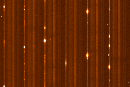
The image above shows a section of a ThAr arc spectrum obtained with CYCLOPS - each element of the IFU is recorded by UCLES as a single spectrum with spectral FWHM=2.55 pixels. In this image, three fibres are missing (fibres 2,3 and 6) producing a distinctive pattern on the spectrograph.
The image above shows a section of a V=14 star observed to measure Doppler velocities, along with a ThXe spectrum injected through the simultaneous calibration fibre.